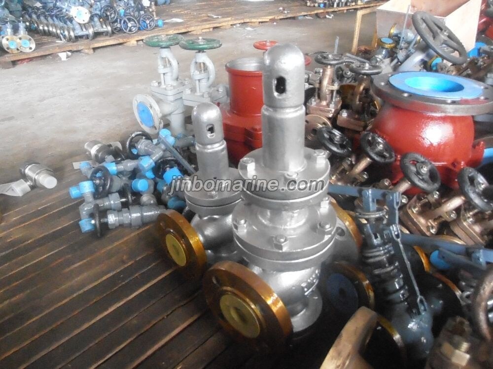
Marine Cast Steel Steam Pressure Reducing Valveis used in the marine steam pipe system with the temperature not over 300 degree centigrade.
Design Standard: GB/T1852-1993
Flange Size as per GB569 or GB2501
Test Standard: GB600
CB Marine Pressure Reducing Valve
Marine Cast Steel Steam Pressure Reducing Valveis used in the marine steam pipe system with the temperature not over 300 degree centigrade. Design Standard: GB/T1852-1993 Flange Size as per GB569 or GB2501 ...
Marine Cast Steel Steam Pressure Reducing Valveis used in the marine steam pipe system with the temperature not over 300 degree centigrade.
Design Standard: GB/T1852-1993
Flange Size as per GB569 or GB2501
Test Standard: GB600
Body-Cast Steel (ZG230-450)
Bonnet-Cast Steel (ZG230-450)
Diaphragm-Bronze (QSn6.5-0.1)
Main Valve Spring-Chrome-Vanadium Spring Steel Wire (50CrVA)
Auxiliary Valve Spring-Chrome-Vanadium Spring Steel Wire (50CrVA)
Regulating Spring-silico-manganese spring steel wire
| Nominal Diameter(mm) | Inlet DN1 | 20 | 25 | 32 | 40 | 50 | 65 | 80 | 100 | 125 | 150 |
| Outlet DN2 | 25 | 32 | 40 | 50 | 65 | 80 | 100 | 125 | 150 | 200 | |
| Steam Pressure (Mpa) | Inlet Pressure P1 | 0.4~2.5 | |||||||||
| Outlet Pressure P2 | 0.2~0.6 | ||||||||||
| 0.6~1.2 | |||||||||||
*The pressure difference between the inlet and the outlet can not be less than 0.2Mpa.
Flange size as per GB569
| Nominal Diameter | Dimension | Body Thickness | Flange Size | Weight | ||||||||||||||||
| PN2.5 Mpa Inlet | PN1.6 Mpa Outlet | |||||||||||||||||||
| DN1 | DN2 | L | H | h | D1 | D2 | D3 | d1 | n1 | Th1 | b1 | D4 | D5 | D6 | d2 | n2 | Th2 | b2 | kgs | |
| 20 | 25 | 170 | 250 | 75 | 6 | 95 | 68 | 48 | 13 | 4 | M12 | 11 | 105 | 73 | 56 | 13 | 4 | M12 | 12 | 15 |
| 25 | 32 | 105 | 73 | 56 | 12 | 115 | 83 | 64 | 15 | 6 | M14 | 13 | 16 | |||||||
| 32 | 40 | 200 | 260 | 80 | 7 | 115 | 83 | 64 | 15 | 6 | M14 | 13 | 125 | 93 | 74 | 21 | ||||
| 40 | 50 | 210 | 270 | 85 | 125 | 93 | 74 | 135 | 103 | 84 | 23 | |||||||||
| 50 | 65 | 240 | 290 | 115 | 135 | 103 | 84 | 170 | 132 | 110 | 17 | 8 | M16 | 15 | 24 | |||||
| 65 | 80 | 300 | 170 | 132 | 110 | 17 | 8 | M16 | 15 | 185 | 147 | 126 | 16 | 40 | ||||||
| 80 | 100 | 280 | 320 | 120 | 8 | 185 | 147 | 126 | 16 | 205 | 167 | 146 | 10 | 43 | ||||||
| 100 | 125 | 330 | 350 | 150 | 9 | 205 | 167 | 146 | 10 | 225 | 187 | 168 | 72 | |||||||
| 125 | 150 | 380 | 360 | 190 | 11 | 240 | 196 | 172 | 21 | M20 | 19 | 255 | 217 | 196 | 12 | 20 | 90 | |||
| 150 | 200 | 470 | 425 | 225 | 13 | 270 | 226 | 200 | 12 | 20 | 325 | 281 | 254 | 21 | M20 | 120 | ||||
Flange size as per GB2501
| Nominal Diameter | Dimension | Body Thickness | Flange Size | Weight | ||||||||||||||||
| PN2.5 Mpa Inlet | PN1.6 Mpa Outlet | |||||||||||||||||||
| DN1 | DN2 | L | H | h | D1 | D2 | D3 | d1 | n1 | Th1 | b1 | D4 | D5 | D6 | d2 | n2 | Th2 | b2 | kgs | |
| 20 | 25 | 170 | 250 | 75 | 6 | 105 | 75 | 58 | 14 | 4 | M12 | 16 | 115 | 85 | 68 | 14 | 4 | M12 | 16 | 16 |
| 25 | 32 | 115 | 85 | 68 | 140 | 100 | 78 | 18 | M16 | 18 | 17 | |||||||||
| 32 | 40 | 200 | 260 | 80 | 7 | 140 | 100 | 78 | 18 | M16 | 18 | 150 | 110 | 88 | 22 | |||||
| 40 | 50 | 210 | 270 | 85 | 150 | 110 | 88 | 165 | 125 | 102 | 24 | |||||||||
| 50 | 65 | 240 | 290 | 115 | 165 | 125 | 102 | 20 | 185 | 145 | 122 | 20 | 26 | |||||||
| 65 | 80 | 300 | 185 | 145 | 122 | 8 | 22 | 200 | 160 | 133 | 8 | 42 | ||||||||
| 80 | 100 | 280 | 320 | 120 | 8 | 200 | 160 | 133 | 24 | 220 | 180 | 158 | 22 | 46 | ||||||
| 100 | 125 | 330 | 350 | 150 | 9 | 235 | 190 | 158 | 22 | M20 | 250 | 210 | 184 | 74 | ||||||
| 125 | 150 | 380 | 360 | 190 | 11 | 270 | 220 | 184 | 26 | M24 | 26 | 285 | 240 | 212 | 22 | M20 | 24 | 96 | ||
| 150 | 200 | 470 | 425 | 225 | 13 | 300 | 250 | 212 | 340 | 295 | 268 | 12 | 127 | |||||||