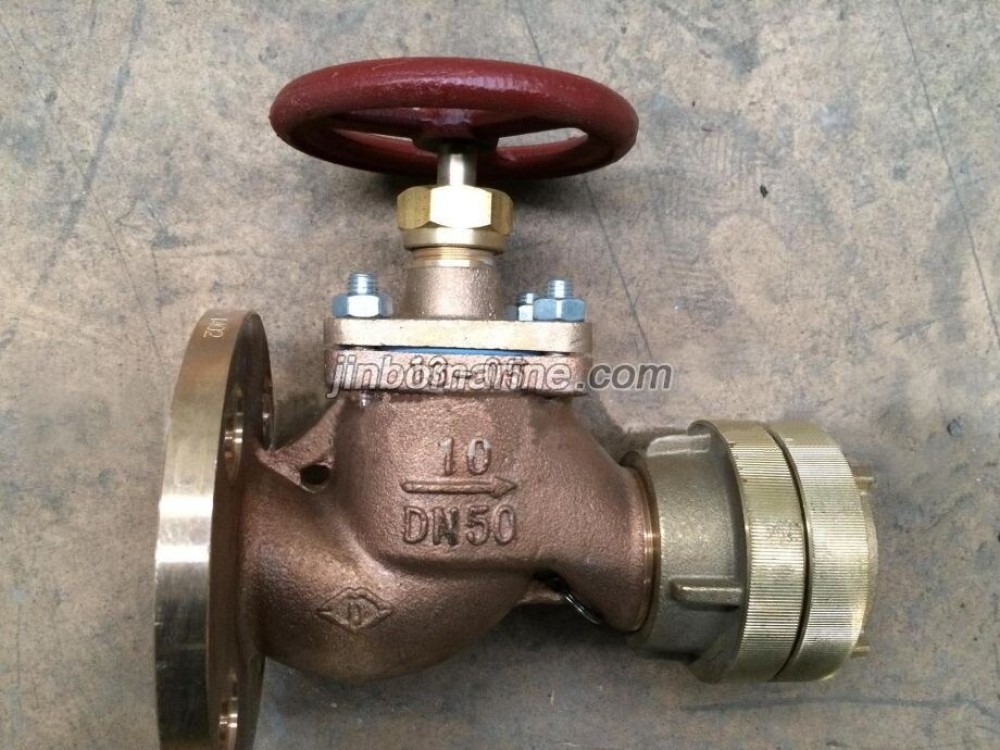
Marine Flanged Fire Hydrant Valve GB/T2032-93 Type B/BS is the hose valve for fire-fighting system in the vessels, also called as marine fire valve.
Jinbo Marine
Marine & Offshore Equipment Datasheet
Product Datasheet
GB Marine Fire Hydrant
Marine Straight Fire Hydrant Valve GB/T2032-93 Type A/AS
Marine Flanged Fire Hydrant Valve GB/T2032-93 Type B/BS is the hose valve for fire-fighting system in the vessels, also called as marine fire valve. Technical Specification: Design Standard: GB/T2032-93, CBM...
ISO9001 Supplier
Class Certificate
Export Supply
Key Highlights
Category
GB Marine Fire Hydrant
Standard
JIS
Material
Bronze or Brass
Weight / Size
GB600 Flange size as per GB569, GB2501.
Certificate
CCS, BV, ABS, GL, LR, DNV, NK,RINA, KR,IRS
We can supply according to your requirement, drawings, class certificate needs, and delivery schedule.
Technical Specifications
Category
GB Marine Fire Hydrant
Model / SKU
Marine-Straight-Fire-Hydrant-Valve-GB-T2032-93-Type-A-AS
Standard
JIS
Material
Bronze or Brass
Weight / Size
GB600 Flange size as per GB569, GB2501.
Certificate
CCS, BV, ABS, GL, LR, DNV, NK,RINA, KR,IRS
Warranty
12 Months unless specified otherwise
Origin
China
China Marine Straight Fire Hydrant Valve GB/T2032-93 Type A/AS:
Technical Specification:
Design Standard: GB/T2032-93, CBM1107-82
Test Standard: GB600
Flange size as per GB569, GB2501. Also be as per JIS, DIN, ANSI, BS standard. The adaptor can be Chinese type, BS type, Storz Typa, ANSI type, Nakajima type.
| Nominal Pressure (Mpa) | Nominal Diameter (mm) | Applicable Medium |
| 1.0 | 40--65 | Sea water, fresh water |
Main Parts & Material:
Body-Bronze or Brass
Bonnet-Bronze or Brass
Disc-Bronze or Brass
Stem-Bronze
Seal Face-Bronze or Brass
Adaptor-Brass
Main Size List(mm):
Type A/B (Flange as per GB569):
| DN (mm) | Structure Dimension | Thickness δ | Flange | Bolt | hand wheel | Lift Range m | Weight(kg) | ||||||||||||||
| L | L1 | H1 | L2 | H2 | |||||||||||||||||
| A | B | A | B | A | B | D | D1 | D2 | d0 | b | n | Th. | Do | S | A | B | |||||
| 40 | 240 | 134 | 85 | 70 | 181 | 154 | 90 | 70 | 5 | 125 | 93 | 74 | 14 | 14 | 6 | M14 | 120 | 11 | 14 | 6.25 | 5.75 |
| 50 | 258 | 145 | 85 | 80 | 189 | 156 | 100 | 80 | 5 | 135 | 103 | 84 | 14 | 14 | 6 | M14 | 120 | 11 | 16 | 7.82 | 7.27 |
| 65 | 294 | 170 | 100 | 95 | 220 | 125 | 120 | 90 | 6 | 155 | 123 | 104 | 15 | 14 | 6 | M14 | 140 | 12 | 20 | 9.80 | 9.40 |
Type AS/BS (Flange as per GB2501):
| DN (mm) | Structure Dimension | Thickness δ | Flange | Bolt | hand wheel | Lift Range m | Weight(kg) | ||||||||||||||
| L | L1 | H1 | L2 | H2 | |||||||||||||||||
| AS | BS | AS | BS | AS | BS | D | D1 | D2 | b | d0 | n | Th. | Do | S | AS | BS | |||||
| 40 | 225 | 130 | 80 | 65 | 181 | 154 | 80 | 65 | 5 | 150 | 110 | 88 | 16 | 18 | 4 | M16 | 120 | 11 | 14 | 7.25 | 6.65 |
| 50 | 238 | 145 | 85 | 75 | 189 | 156 | 85 | 75 | 5 | 165 | 125 | 102 | 17 | 18 | 4 | M16 | 120 | 11 | 16 | 8.94 | 8.27 |
| 65 | 284 | 170 | 100 | 95 | 220 | 190 | 110 | 90 | 6 | 185 | 145 | 122 | 17 | 18 | 4 | M16 | 140 | 12 | 20 | 10.70 | 10.30 |
The size when working pressure is 3Mpa
| DN (mm) | Structure Dimension | Thickness δ | Flange | Bolt | hand wheel | Lift Range m | Joint | Weight(kg) | ||||||||
| L | H1 | H | ||||||||||||||
| D | D1 | D2 | d0 | b | n | Th. | Do | S | d0 | |||||||
| 40 | 62 | 90 | 326 | 5 | 125 | 93 | 74 | 15 | 14 | 6 | M14 | 120 | 11 | 11 | G1-1/2 | 7.6 |
| 50 | 75 | 95 | 353 | 6 | 135 | 103 | 84 | 15 | 14 | 6 | M14 | 140 | 11 | 14 | G2 | 9.8 |
| 60 | 82 | 115 | 416 | 7 | 170 | 132 | 110 | 17 | 17 | 8 | M16 | 160 | 12 | 18 | G2-1/2 | 12.6 |
A/AS-Straight Type
B/BS-Angle Type