
_300x225.webp)


Marine Equipment
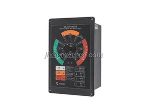
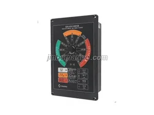
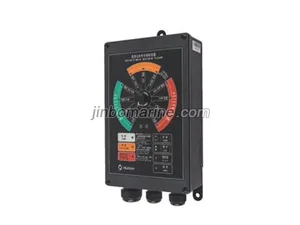
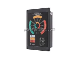
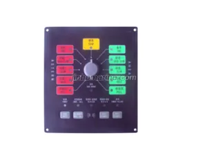
GCCZ-04 Marine Telegraph Engine Room Receiver
The GCCZ main transmission clock system consists of instruments such as a transmitter and receiver. The transmitter is powered by the display screen Composed of circuit, control...

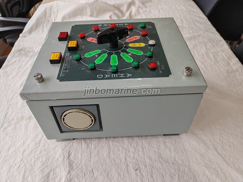

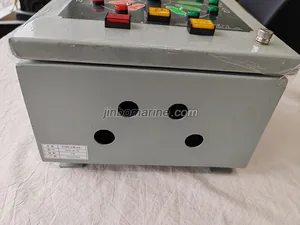
GCCZ-04 Marine Telegraph Engine Room Receiver
 PDF Datasheet
We can supply according to your requirement.
China GCCZ-04 Marine Telegraph Engine Room Receiver:
The GCCZ main transmission clock system consists of instruments such as a transmitter and receiver. The transmitter is powered by the display screen
Composed of circuit, control circuit, and out of step alarm circuit; The receiver consists of a display circuit and a step out alarm circuit.
The electronic light transmission clock can simultaneously display the parking spaces of both the transmitter and receiver, and whenever the transmitter emits a change
When the command to change the operation status of the host is given, the out of step alarm circuit of the transmitter works, and the out of step alarm light is emitted
Audio signal (LED flashing, alarm sounding), the out of step alarm is cleared after the cabin command is completed.
The electronic light transmission clock can be equipped with both AC and DC power sources. AC as the main power source, DC as the application
Emergency power supply. When the AC power supply is cut off, the DC power supply is automatically put into operation.
The function of the transmitter is to indicate the current handle position. When the handle position is the same as the receiver position, the indicator light is
Flat light, when the command issued by the transmitter handle changes, the corresponding indicator light will light up and flash simultaneously until received
The transmitter will synchronize and flatten the light. When the three ground control systems produce monitoring room receivers, the transmitters and cabin receivers
During communication, these 11 lights indicate the position of the driver's cab transmitter handle.
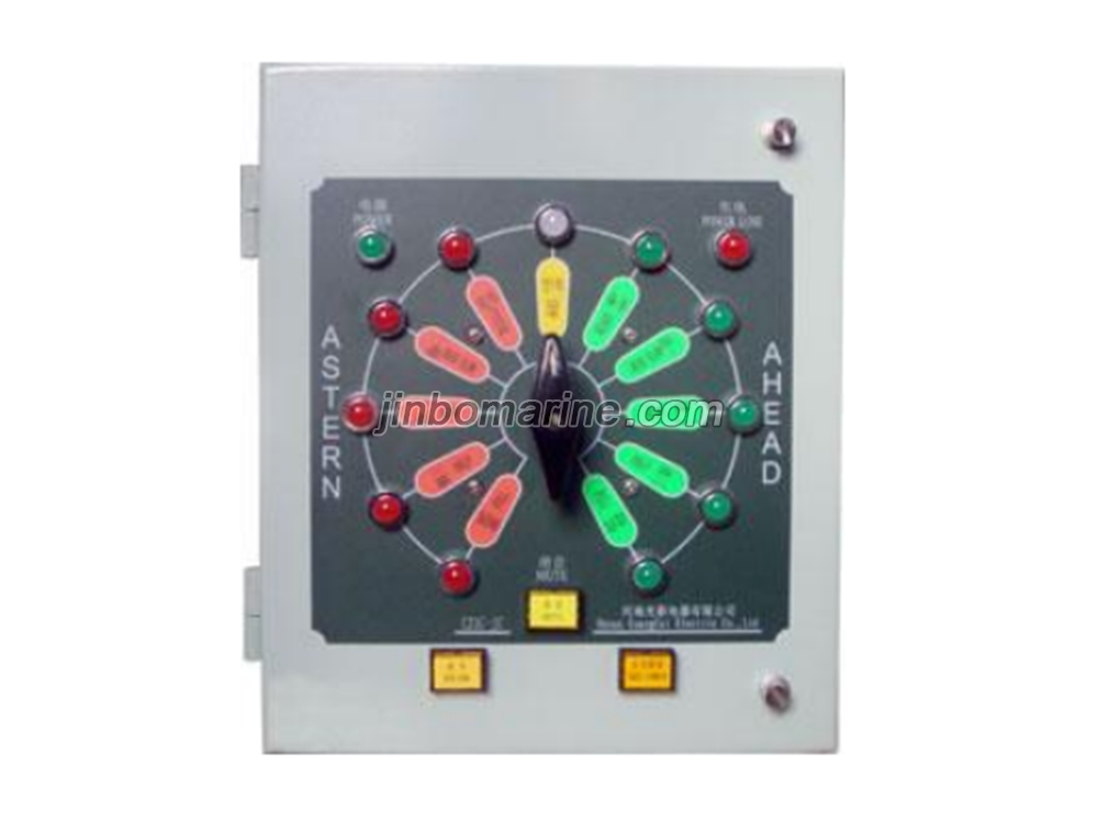
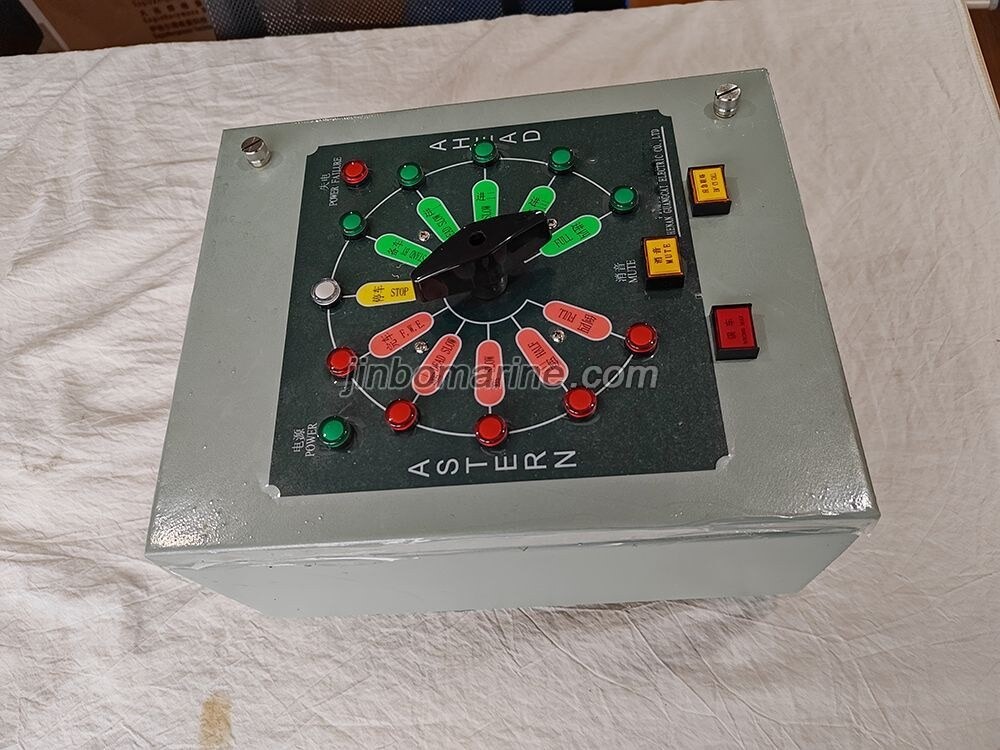
The function of the receiver is to indicate the current position of the receiver handle. When the position of the transmitter handle is in line with the position of the receiver
At the same time, the indicator light is flat. When the command issued by the receiver handle changes, the corresponding indicator light will light up
Flash frequency until the transmitter returns synchronization and flattens the light. When the three control stations produce a monitoring room receiver, the transmitter
When communicating with the cabin receiver, these 11 lights indicate the position of the cabin receiver handle.
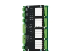
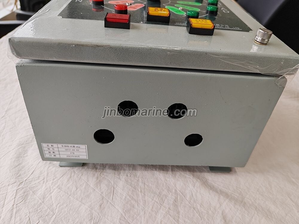
1. Main output terminals (28)
Position indicator lights for the transmitter handle: Forward 1, Forward 2, Forward 3, Forward 4, Backup, Parking, Completed
Back 1, Back 2, Back 3, Back 4, a total of 11;
Receiver position indicator lights: Forward 1, Forward 2, Forward 3, Forward 4, Backup, Parking, Finished, Rear
Step back 1, Step back 2, Step back 3, Step back 4, a total of 11;
1 power-off alarm light;
Sound alarm signal (with relay output);
One 485 communication interface (occupying two terminals).
2. Main input ports (15)
Command input signals: forward (backward) 1, forward (backward) 2, forward (backward) 3, forward (backward)
4. Backup (completion) and parking signals, a total of 11;
One input signal for power loss signal (photoelectric isolation);
One feedback signal (photoelectric isolation) for the merging of the main train;
One reverse combined feedback signal (photoelectric isolation);
Cancel one missed train alarm signal (photoelectric isolation);
Control terminal for communication between monitoring room and cab, as well as communication between cabin and cab (photoelectric isolation);
Signal transmitter (cab), receiver (monitoring room), receiver (cabin), repeater, left and right aircraft
Set the DIP switch (three positions).